
Guides / Slicers and calibration
Supports, infill and walls: spend material where it works
For many functional parts, orientation and shell design matter more than simply pushing infill towards 100 per cent.
Start here
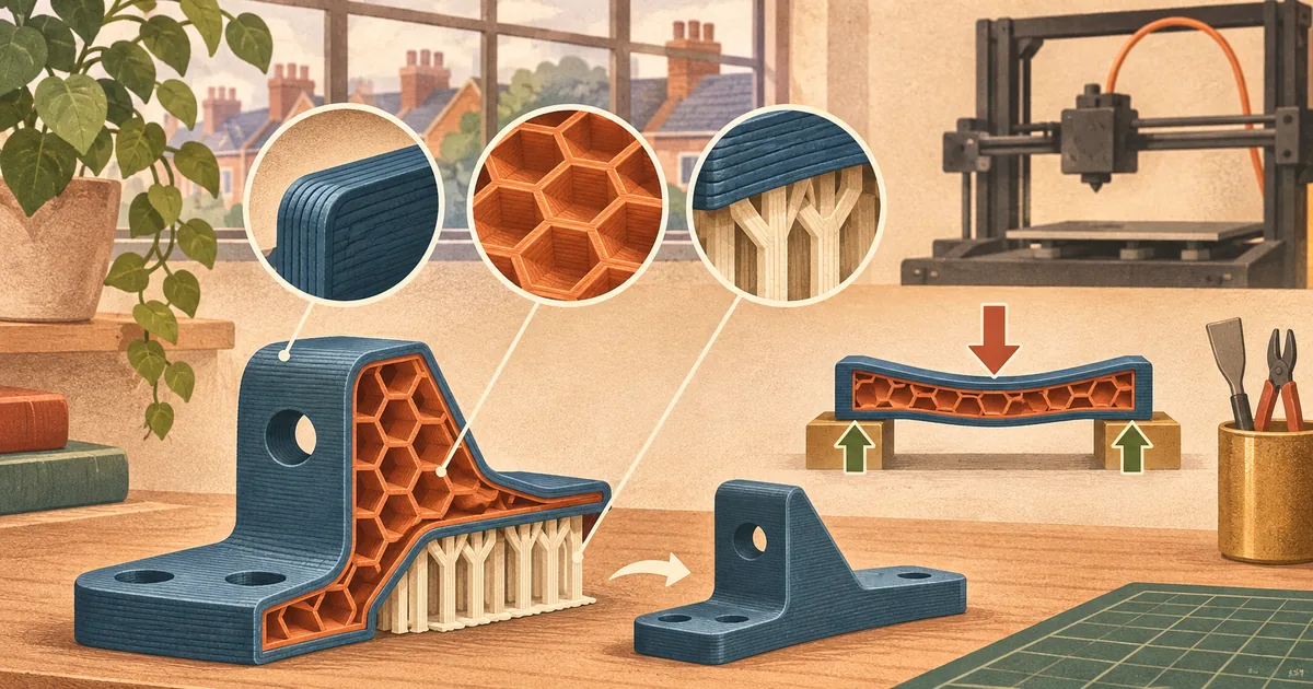
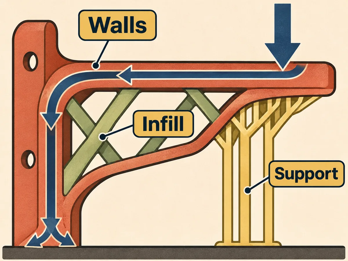
Before dragging infill towards 100 per cent, look at the load path. Orientation, walls and the material around holes or fasteners often do more useful work than filling every quiet space inside the model.
UltiMaker describes infill as an internal structure balancing strength, weight, material and time. Loads rarely act equally in every direction, so orient the part and its layer lines for the real load, add material around holes and fasteners, and use walls and top or bottom layers deliberately.
Support is temporary process material, not part strength. Rotate the model to reduce inaccessible support and protect important surfaces. Use the slicer's preview to check floating islands, bridge direction, wall count around thin features and whether a top surface is adequately supported. For safety-critical or highly loaded parts, use an appropriate engineering design process rather than relying on rules of thumb.
Walls first: where the strength usually lives
Prusa's layers and perimeters article is blunt about it: the strength of a model is mostly defined by the number of perimeters, not the infill, so if you want a stronger print, add perimeters. Original Prusa profiles use a minimum of two. That fits what you'll often see on snapped brackets and hooks: the break runs along a layer line or through a thin shell, while the infill inside barely mattered.
A few practical consequences follow:
- Count perimeters in millimetres, not just loops. Two loops of a 0.45 mm line are under a millimetre of shell. Around a screw hole or a heat-set insert, three or four loops put solid plastic where the thread or knurl actually bites.
- Keep the infill bonded to the walls. UltiMaker's Cura infill settings article explains that a higher infill overlap usually bonds infill and walls better, at the risk of the pattern showing through the outer surface. Its "infill wipe" travel strengthens the joint but can leave marks on the outside.
- Mind the print order. The same UltiMaker article frames "infill before walls" as a trade-off: walls printed first can sag with nothing to attach to on overhangs, while printing walls first stops infill pushing out and shining through. Pick the one that suits the part, not a forum default.
Layer height feeds into this too. Prusa advises keeping layer height below about 80 per cent of the nozzle diameter (roughly 0.32 mm for a 0.4 mm nozzle) and notes that layer height changes only the vertical resolution, so embossed text lying flat on the bed looks the same at any layer height.
Infill patterns: what each one is for
Infill pattern names sound interchangeable. They aren't, and both Prusa and UltiMaker document real differences.
- Gyroid. Prusa's infill patterns guide calls it one of the few 3D structures that supports well in every direction, prints relatively quickly and doesn't self-intersect within a layer. UltiMaker adds that it is equally strong in all directions but not very stiff, and that it can take a long time to slice and produce large G-code files.
- Grid, triangles and similar crossing patterns. Grid is quick and supports top surfaces well, but the paths cross within a layer. Prusa warns that material builds up at the crossings, which can cause noise or even a failed print. UltiMaker says crossing patterns can cause nozzle collisions and vibration, and tells owners of some of its own printers to avoid them altogether.
- Cubic and adaptive cubic. Cubic builds corner-down cubes. Adaptive cubic gets denser near walls and top and bottom surfaces and leaves the middle sparse; Prusa puts its material use at about a quarter less than rectilinear while keeping similar mechanical properties.
- Lightning. Branches grow only where top surfaces need holding up. Both makers say it saves a lot of material but adds no strength, so it's for display pieces, not brackets.
- Rectilinear at 100 per cent. Prusa says rectilinear is the only pattern it recommends for fully solid infill, and PrusaSlicer switches to it automatically if you set 100 per cent density.
UltiMaker also documents gradual infill, which halves the density in steps further down from the top surface. It saves time but lowers the strength of the part, and UltiMaker recommends it for visual models only. Keep it off functional parts.
Supports: pick the type, then the gap
Prusa's support material guide suggests trying a different orientation, or splitting the model into parts, before generating anything, because fewer overhangs means less support to remove. When you do need them, the main choices are:
- Grid-based supports are stable but can spread out along the part's walls. Prusa's snug variant follows the overhang's outline more closely, at the cost of less stable tall, thin pillars.
- Organic (tree) supports branch up from the bed and thicken where the model needs them. Prusa's Organic supports article describes them as easy to remove, unlikely to scar the surface, and fast and cheap to print. It also credits Cura and Thomas Rahm's tree-support work as their origin. Branch angle, tip diameter and branch distance trade stability and overhang quality against how easy the supports are to remove.
The settings that decide how clean the underside is are the top contact Z distance (the gap between the support interface and the part) and the interface layers. A bigger gap releases more easily but leaves a rougher, droopier surface; Prusa pairs a zero gap with soluble or breakaway interface materials rather than ordinary same-material supports. Prusa recommends switching on top support interfaces instead of raising branch density when you need a dense contact surface. Use support blockers to remove supports from places you know can bridge, enforcers to support only the few spots that need it, and painted-on supports for fine control. Prusa also suggests placing an enforcer mid-span to split a long bridge into two shorter, cleaner ones.
One safety point from the same Prusa page: support fragments can be sharp and can fly off when they snap free, so wear eye protection when you're levering out stubborn supports.
Seams and ironing: the finishing settings
The seam is where each perimeter loop starts and ends, and it's also a weak spot. Prusa's seam position article explains the options. Nearest tucks it into concave corners. Aligned stacks it into one vertical line. Rear pushes that line to the back for display parts. Random scatters small zits across the surface but, according to Prusa, increases overall strength. Staggered inner seams and the newer scarf seams (overlapping ramps on smooth contours) reduce the weak line further, at the cost of extra print time.
Ironing runs the hot nozzle back over flat top surfaces with a tiny extrusion to smooth them. It's worth using on lids, nameplates and parts that must sit flush against each other, but Prusa notes that it adds print time, can leave edges slightly fuzzy, and does little for round or organic shapes. On large areas, some machines can suffer heat creep and a clogged hotend, mainly with PLA. Often the better trick is to flip the part over so the show face prints against the build plate.
The short version
Spend material where the load travels: useful walls, supported top surfaces and enough material around fasteners. Choose infill for its job (gyroid or cubic for general parts, lightning only when nothing loads the part), use organic supports with sensible interfaces, and inspect the sliced layers. More infill is a setting; a stronger part starts with the design and orientation.