
Guides / Design and finishing
Best deburring and finishing tools for FDM prints
Match cutters, scrapers, files and abrasives to the mark you need to remove, with dust and blade safety built into the sequence.
We haven't tested these products. This comparison is based on makers' published specifications and manuals, retailer listings and owner reviews (checked 15 November 2026).
Choose the least aggressive tool that works
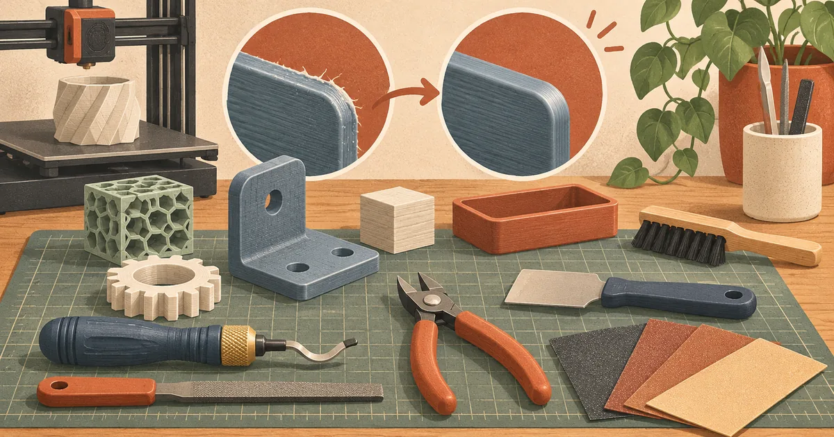
FDM finishing is controlled material removal. Flush cutters separate a support branch; a deburring blade shaves a raised rim; a file reaches a slot; abrasive paper levels broad surfaces. Using one sharp blade for every mark makes slips, gouges and changed dimensions more likely.
Start by deciding what the surface must do. A hidden support scar needs only to stop fouling an assembly. A painted prop needs a gradual abrasive sequence and compatible coating. A locating face needs to remain flat and dimensionally honest. Those are three different finishing jobs, even if they begin with the same printed polymer.
A task-based buying table
| Defect or stage | First-choice tool | Why it suits the job | Main trap |
|---|---|---|---|
| Support branches | Small flush cutters or narrow pliers | Removes the structure in short, controllable sections | Twisting the whole support and tearing the model wall |
| Brim and sharp edge | Guarded swivel deburring tool | Follows an outside contour with light pressure | Letting the blade dive into a soft corner |
| Hole or narrow slot | Needle file of matching shape | Cuts locally while preserving the opposite face | Enlarging a functional fit without measuring |
| Layer lines on a broad face | Abrasive paper on a flat block | Spreads pressure and helps keep the face planar | Fingertip sanding that creates hollows |
| Final paint preparation | Fine abrasive and compatible primer system | Produces a uniform key for the coating | Mixing products without checking safety data or cure times |
An interchangeable-blade deburring handle is useful for convex edges and holes, but it does not replace files. A flat, half-round and round needle file set covers straight faces, curves and bores. For abrasive paper, a modest progression matters more than owning every printed grit number: change only when the previous scratches are even, and use a block wherever flatness matters.
Relevant Amazon UK listings
The listing titles establish what is being sold; they do not establish suitability for every plastic or prove the stated grit and steel specifications.
- KAIHAOWIN flush cutters, pack of ten: See it on Amazon UK
- AFA Tooling deburring tool with 11 M2 blades: See it on Amazon UK
- STEBRUAM wet-and-dry sandpaper set, 120 to 3000 grit, 42 sheets: See it on Amazon UK
Retail prices are deliberately omitted. Black Friday promotions run to around 1 December 2026 and can move quickly, so compare live prices and replacement-blade availability before ordering.
Improve the print before reaching for a blade
Post-processing begins in the slicer. UltiMaker's Cura support guide explains that normal supports offer large contact areas but can scar more, while tree supports branch around the model and may reduce scarring but are not suitable for every material. The guide also describes support-interface density and gaps: stronger contact can improve the underside yet become harder to remove.
Preview where support touches a cosmetic or mating face. Try an orientation that moves contact to a hidden surface, or divide the model if a sound joint is possible. Do not reduce the support gap blindly: a beautifully supported underside is a poor bargain if the interface becomes part of the model.
For a repeat part, print a small section containing the actual overhang and interface. Change only the support style, contact spacing or orientation under review. The goal is not a generic “perfect underside”; it is a surface that meets the part's purpose with acceptable removal work.
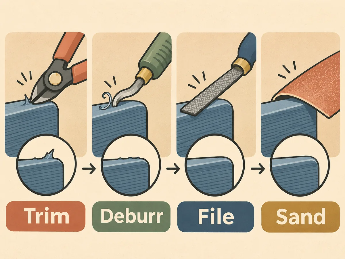
A safer finishing sequence
- Let the part return to room temperature. Warm thermoplastic is easier to deform, and a warm build sheet may still be gripping the base strongly.
- Protect the critical face. Mark dimensions and surfaces that must not be cut. Tape can reduce incidental scratches on an adjacent cosmetic area, but it is not a blade guard.
- Remove support from the outside inward. Break or clip small accessible sections so that stored spring force cannot tear a thin wall. UltiMaker's Breakaway procedure uses pliers and cutting pliers to loosen corners, then removes remaining strands with a knife or tweezers.
- Trim proud material. Place the part on a stable bench support. Keep the cutting path away from the holding hand and take thin shavings rather than forcing a deep cut.
- File local features. Match file shape to geometry, clear the teeth, and check a functional opening frequently with its gauge or mating part.
- Block-sand larger faces. Work through an appropriate coarse-to-fine sequence. Stop as soon as the previous scratches are gone; extra passes only remove dimensions.
- Clean without redistributing dust. Capture debris at source or vacuum it with suitable equipment. Check the filament and coating safety information before wet sanding or applying solvents.
Worked example: preparing a two-part enclosure
Suppose a lid has a brim, four supported clip windows and a broad outer face for paint. Treat each zone separately.
First clip the brim every few centimetres, then shave the remaining lip with the deburring tool while the lid lies flat. Check that the tool has not rounded the mating edge. Next remove support from each clip window with narrow pliers. Use a small flat or square file on the window, taking the same number of light strokes from each side, and test the clip after every short pass.
Do not sand the mating ledge merely because the outer face needs work. Mask or avoid it. Put the broad face on a flat sanding block, use a cross-hatched stroke pattern, and inspect under raking light. Low areas that retain the original layer pattern should not be chased indefinitely if doing so would thin the lid. A compatible filler-primer may be the appropriate next stage, but its technical and safety sheet should govern ventilation, application and curing.
The worked result is not “perfectly smooth everywhere”. It is a lid whose clip windows function, whose sealing edge remains true and whose visible face is consistent enough for its planned coating.
Dust, fragments and heat
Clipped supports can leave the tool quickly, so eye protection should match the projectile risk. HSE's PPE guidance distinguishes protection for impact, dust, splash and heat; ordinary prescription glasses are not automatically suitable eye protection.
Sanding dust deserves source control even when the job looks small. HSE advice on harmful dusts recommends keeping dust to a minimum and using on-tool extraction or local exhaust ventilation for powered sanding. It notes that suitable respiratory protection may also be required depending on extraction. The exact control depends on the polymer, fillers, coating and scale of work, so read the relevant safety data rather than treating all FDM dust alike.
Avoid using a heat gun as a universal surface-finishing tool. It can round detail, relax a loaded part and generate irritating plastic fume. HSE notes that plastic fume composition varies and can irritate eyes, nose and lungs. If a maker specifies heat for a particular post-process, follow its temperature, distance, ventilation and PPE directions instead of experimenting on a finished functional part.
Mistakes that spoil dimensions
Sanding a hole with rolled paper. The roll follows pressure rather than a datum and can make the bore bell-mouthed. A matching round file used evenly, followed by measurement, is easier to control.
Starting too coarse. Deep scratches consume more material at every later stage. Begin with the mildest abrasive that levels the defect in a reasonable time.
Deburring towards a finger. Reposition the work, clamp it with protected jaws or change tool. The part is replaceable; a hand is not a workholding fixture.
Polishing a joint face by eye. A glossy surface can still be crowned. Use a flat block and a simple witness mark, then check the part against its mating surface.
Painting over loose support residue. Coating does not stabilise an incompletely removed interface. Trim and clean it first, then follow the coating maker's preparation instructions.
The practical shortlist
Buy cutters for support, a guarded deburring handle for edges, three useful file shapes and abrasive sheets with a flat block. Add calipers if the finished feature has to fit. Spend the setup time on workholding, dust control and slicer support contacts: those choices improve both safety and the surface, while a more aggressive blade merely removes material faster.