
Guides / Design and finishing
Best heat-set insert tools for printed parts
Choose controlled heat, a piloted tip and square guidance, then design the printed boss around the insert maker's hole data.
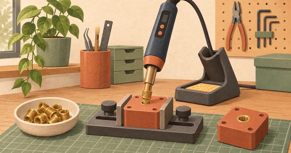
We haven't tested these products. This comparison is based on makers' published specifications and manuals, retailer listings and owner reviews (checked 15 November 2026).
The hole and boss matter as much as the iron
A heat-set insert works when softened thermoplastic flows into the insert's external features and then solidifies without splitting or badly distorting the boss. The tool supplies heat and guidance; it cannot rescue an incorrect hole diameter, too little surrounding material or an insert intended for a different installation method.
For occasional M3 hardware, a temperature-controlled soldering iron with a matching piloted insert tip is the useful minimum. A vertical press or guided stand becomes attractive when several inserts must sit square and at the same depth. The stand improves alignment and repeatability, but it still needs a stable part fixture and a positive depth reference.
Tool choices compared
| Setup | Best suited to | Advantages | Limits to check |
|---|---|---|---|
| Hand iron with conical soldering tip | A trial piece or very occasional insert | Uses equipment you may own | Small contact area can mark threads or encourage a tilted push |
| Hand iron with piloted insert tip | Low-volume hobby assembly | Tip locates in the insert and transfers heat more evenly | Squareness still depends on your hand and view |
| Guided stand with depth stop | Repeated bosses on enclosures or jigs | Controls approach angle and stopping height | Cheap stands may have play; work still needs fixturing |
| Dedicated heat-insertion machine | Production and documented processes | Controlled force, heat and stops | Cost and scale are excessive for most home benches |
SPIROL's UK inserts design guide describes a piloted tip for guidance and says heat installation should soften, not melt, the plastic. It also describes low insertion pressure and a positive stop for a flush result. Those principles explain why a broad, correctly sized tip and a straight guide are more valuable than a high-wattage iron used without control.
Relevant Amazon UK listings
Check thread pitch, insert outer dimensions, tip diameter, iron compatibility and plug before buying. A bundle containing an M3 tip does not prove that every enclosed M3 insert uses the same recommended hole.
- 310-piece M2–M8 brass heat-set insert kit: See it on Amazon UK
- 415-piece M2–M8 insert and insertion-tool kit: See it on Amazon UK
- M3 heat-set insert tool with brass inserts: See it on Amazon UK
- 100 M3 × D5 × L4 threaded inserts: See it on Amazon UK
No retail figure is fixed here. Black Friday sale prices can change through the period ending around 1 December 2026, so compare the live cost of the sizes you will actually use and the availability of replacement tips.
Design the receiving feature from the insert data
Do not make the CAD hole equal to the screw's nominal diameter. Obtain the insert maker's drawing and use its recommended receiving-hole geometry for the exact series. Measure a sample insert as a cross-check, not as a replacement for that drawing.
SPIROL's hole-design paper gives several transferable design rules: the blind hole should be deeper than the insert, the installed top should be flush, and correct hole size is critical because an oversized hole reduces performance while an undersized one can create stress, cracks and flash. It recommends a minimum depth of insert length plus two thread pitches for its products and describes an optimum boss diameter of two to three times the insert diameter. Apply those figures only to the SPIROL context cited; another insert maker's drawing takes priority for its hardware.
Model a small lead-in that matches the chosen insert style. Give the screw clearance at the bottom so it cannot jack the insert out of a blind hole. In the mating component, make the clearance hole large enough for the screw but small enough that the insert's face or pilot carries against the component. A screw that bears on unsupported printed plastic defeats much of the reason for adding the insert.
Print the boss with sufficient walls around the hole. Slicer infill percentage does not guarantee material immediately beside a narrow cylindrical feature; inspect the preview and add local wall thickness or geometry. Orient the part so the boss is well supported by continuous roads, and keep a weld line or seam away from the most highly stressed side where practical.
Establish the process on a coupon
Create a small coupon containing two or three copies of the real boss, with the same material, layer height, wall settings and orientation as the part. Include enough base material that holding the coupon resembles holding the finished component.
- Verify the iron and cable are sound, fit the correct insert tip cold and arrange a heat-resistant rest.
- Set an initial temperature from the insert and polymer guidance, not from a forum recipe. SPIROL's design guide gives a starting differential above the plastic's initial softening temperature for its industrial process; it also stresses that the correct combination requires experimentation.
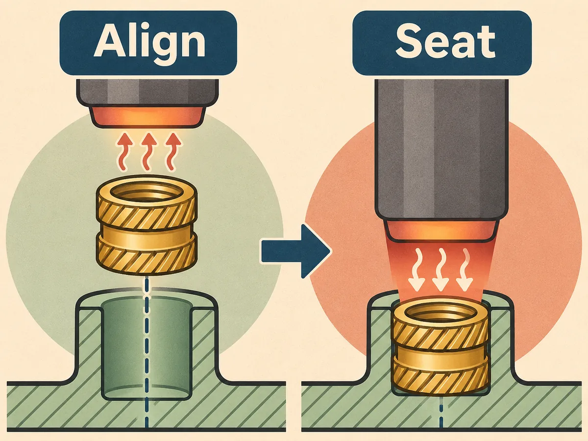
- Place the insert square at the hole entrance before touching it with the hot tip. Support the coupon on a flat, non-flammable surface.
- Apply only enough downward force for the softened plastic to accept the insert. If substantial force is required, stop: the tool may be too cool, the hole too small or the insert mismatched.
- Stop at the planned height and withdraw the tip vertically. Do not “stir” the insert into alignment.
- Let the plastic solidify before inserting a screw or applying side load.
- Section one disposable coupon through the boss. The SPIROL guide suggests inspecting for a negative image of the insert profile in the plastic; voids, a melted cavity or a split boss show that the setup needs work.
Record the insert code, measured hole, material, print orientation, wall setup, iron set-point, tip and depth stop. That record is specific to this joint. Changing from PLA to PETG, adding glass fibre or switching insert series requires another coupon.
Worked example: four M3 inserts in an electronics lid
Begin with the actual M3 insert drawing and design one boss. Make the hole depth include screw clearance, then use a pattern in CAD so all four bosses share the same geometry. In the slicer, inspect each boss layer by layer: the wall paths should surround the hole without a thin gap between wall and infill.
Print a two-boss coupon beside the first lid. Use the first boss to find a workable heat and feed rate, then use the second to check repeatability with the guide stop set. After cooling, place a straight M3 screw in each insert by hand. Resistance at the first thread suggests contamination or tilt; forcing the screw can hide the installation fault and damage the insert.
For the lid, fixture a flat datum rather than gripping a thin cosmetic wall. Install inserts in a sequence that lets the part cool locally instead of reheating one small area repeatedly. Lay a straightedge across the insert faces after cooling. One proud insert can hold the mating component off the lid; one deeply buried insert can make the screw load unsupported plastic.
Failure patterns and corrections
Insert leans to one side. Check play in the stand, whether the work surface is perpendicular to the tip, and whether the insert started square. Reheating and levering an installed insert usually enlarges the cavity; validate a corrected setup on a new coupon.
Plastic forms a large collar. The hole may be undersized, the temperature excessive or the descent too fast. Compare the feature with the insert maker's hole recommendation before trimming away evidence.
Boss splits after cooling. Look for insufficient wall thickness, an undersized receiving hole, incompatible filled material or installation before the insert was adequately heated. SPIROL explicitly notes that filled plastics can require changed hole recommendations.
Insert spins under tightening. Possible causes include an oversized hole, insufficient remelt into the knurl, too little boss material or torque beyond the designed joint. Do not cure it with random adhesive until you understand whether the joint design is adequate.
Screw bottoms before clamping. Increase hole depth or shorten the screw as the design permits. Bottoming can push against the insert and cause jack-out.
Heat and fume controls
Keep the iron in a stable stand, route its cable away from the work and never touch the insert immediately after withdrawal. Brass and the tip retain heat after the surrounding surface appears still. Eye protection is sensible where a springy fixture or clipped plastic can eject fragments.
Use ventilation appropriate to the polymer and any additives. HSE's plastics guidance says the composition of plastic fume varies and that it can severely irritate eyes, nose and lungs; local exhaust ventilation greatly reduces risk. Stop if material chars or smokes, because that is not a normal sign of a well-controlled insertion.
The buying decision
Choose a controlled iron that accepts a proper piloted tip, then add a rigid vertical guide when alignment or quantity justifies it. Buy inserts from a range with usable drawings rather than selecting by thread alone. The best tool cannot compensate for an anonymous insert, an unmeasured hole and a thin boss; a modest guided setup can produce repeatable joints when those three details are designed together.