
Guides / Design and finishing
Design tolerances and orientation for useful prints
Fit is a printer–material–profile result. Use coupons, orient around the load and make clearances intentional instead of copying one universal number.
Start here
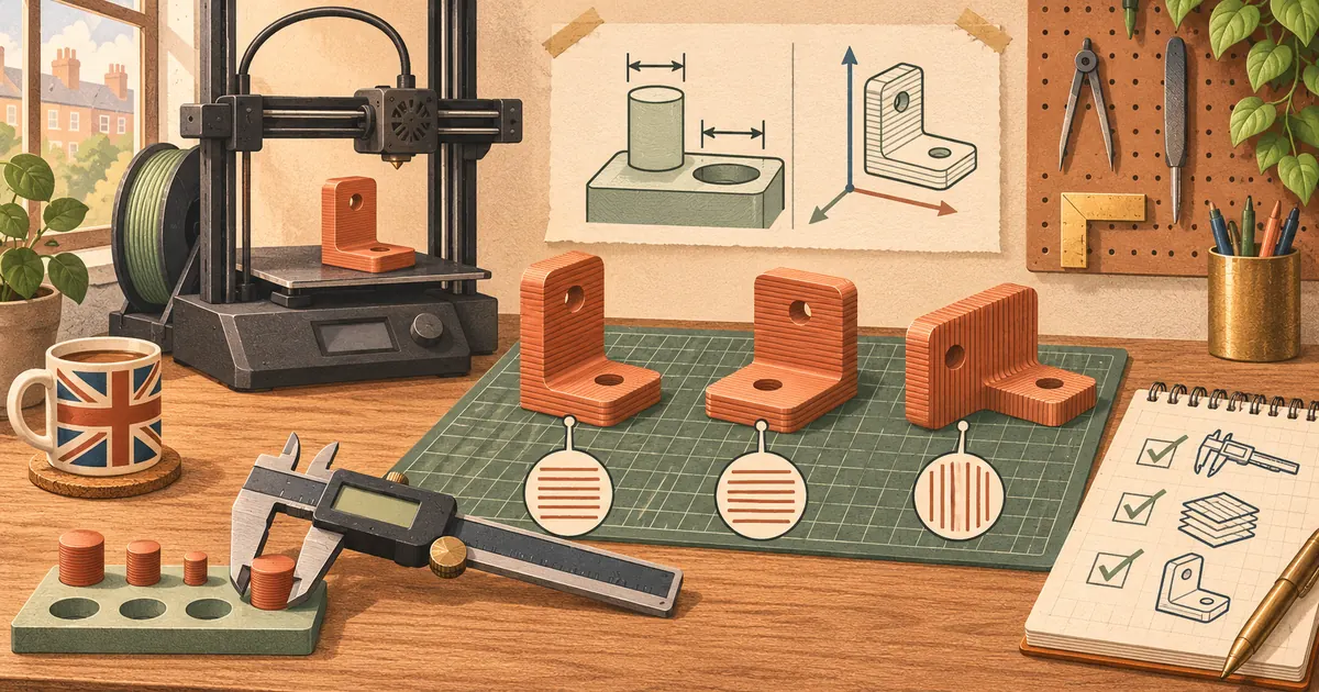
If two printed parts should slide, click or press together, the CAD dimensions are only the beginning. Fit comes from the whole printer–material–profile combination, so make a small coupon and measure the joint you actually care about.
Orientation changes surface quality, support, dimensional behaviour and layer-direction strength. Put critical holes where they can be measured and corrected, add chamfers to lead mating parts together, and avoid thin unsupported horizontal ledges. Preview every layer around the feature. If the part carries a person, restrains a load or guards machinery, a hobby print needs professional engineering judgement and an appropriate factor of safety.
Why one clearance number doesn't travel
You'll often see a single "use 0.2 mm clearance" rule passed around forums. The slicer and printer makers are more cautious. OrcaSlicer's tolerance calibration page says each filament and printer combination can produce different tolerances, and that even the same filament and print profile may behave differently from one printer to another.
Prusa's modelling for 3D printing article makes the same point from the design side: there is no single universal value. It lists horizontal or vertical orientation and the geometry of the interlocking parts among the main factors, notes that materials can warp or shrink during printing, and says an Original Prusa will be accurate to at least 0.2 mm. As a first guess for parts that need to move, such as a hinge, it suggests at least 0.3 mm. Treat that as the opening value on a coupon, not the final answer for every joint.
The type of fit matters as much as the number. A sliding drawer runner, a snap catch, a press-fit bearing pocket and a captured nut each want different behaviour, so a coupon should copy the real joint shape rather than just a generic peg in a hole.
Build a clearance coupon
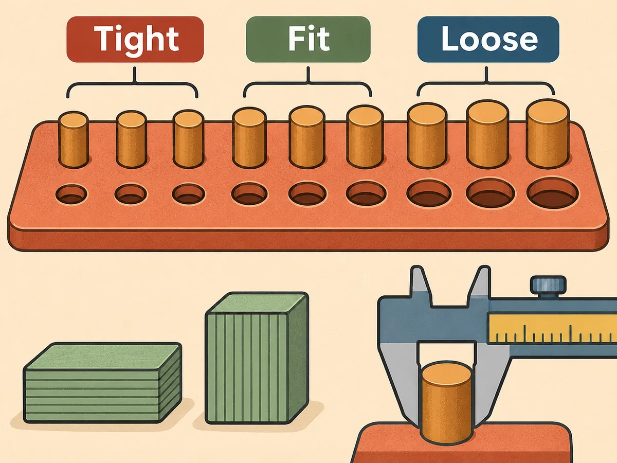
OrcaSlicer ships a ready-made test for this. Right-click the plate in Prepare mode and choose "Add Handy Model" to find it. According to the OrcaSlicer wiki, the model has a base with six hexagonal holes at 0.0, 0.05, 0.1, 0.2, 0.3 and 0.4 mm tolerance, plus a printed hexagon tester. You can check the holes with a 6 mm Allen key or the tester, and measure both with calipers. OrcaSlicer suggests running it as part of the order set out in its calibration guide, so flow and pressure advance are already sensible before you judge fit.
For your own designs, make a coupon in CAD with the actual feature repeated at several clearances and an engraved label beside each one. Print it in the same orientation as the final part. A hole printed vertically (its axis pointing up) and one printed lying on its side come out differently, which is one of the factors Prusa names above.
Holes, contours and polyholes in the slicer
When a whole family of parts is consistently tight, the slicer can correct it instead of every CAD file. OrcaSlicer's precision settings include X-Y hole compensation and X-Y contour compensation. Positive hole values make holes bigger and negative values make them smaller; contour compensation does the same for outside edges. The wiki describes these as small corrections for assembly issues caused by things like filament type, temperature or calibration, and points you back to the tolerance test to find the value.
The same page explains a subtle reason walls measure differently between slicers. Slic3r and its forks (PrusaSlicer, SuperSlicer and OrcaSlicer) model the extrusion as an oval, so lines overlap. Two 0.4 mm walls at 0.2 mm layer height add up to about 0.714 mm, not 0.8 mm. Cura assumes a rectangular line with no overlap, so two 0.4 mm walls give 0.8 mm. OrcaSlicer's Precise wall option removes the overlap between the outer wall and the next wall in, which the wiki says improves size accuracy and layer consistency.
Two more OrcaSlicer options help with fits:
- Convert holes to polyholes prints circular holes as polygons with fewer, flat sides, a technique the wiki credits with producing openings closer to the intended diameter.
- Precise Z height adjusts the last few layers so a 20.1 mm tall object comes out at 20.1 mm instead of rounding up to the next 0.2 mm layer.
Elephant's foot: the first-layer lip
The first layer is squished onto a heated bed, so it usually ends up a little wider than the layers above. Prusa's elephant foot compensation article explains that this matters most when parts need precise dimensions or tight fits. PrusaSlicer's setting (Print settings, Advanced, available in Advanced or Expert mode) shrinks the first layer instead of making you sand the lip off. Prusa says values around 0.2 mm usually work for the default 0.4 mm nozzle, and its official profiles switch it on by default.
There's a trade-off: a brim attaches more weakly when compensation is on. If the brim no longer connects at all, Prusa says the value is probably too high. OrcaSlicer goes a step further with Elephant foot compensation layers. Its wiki shows the correction fading out in a straight line. With 0.25 mm over five layers, layer 2 gets 0.2 mm, layer 3 gets 0.15 mm and so on until layer 6 gets none. Compensation is skipped when a raft is used.
On the design side, a small chamfer on bottom edges that mate with something hides any remaining lip and helps parts start together.
Orientation for strength, surface and supports
Prusa's modelling guide compares FFF parts to wood: they are stronger in one direction than another, so structural parts should be oriented for strength. In practice, try to keep the main bending or pulling load running along the layers rather than trying to peel them apart. A bracket printed so its load tries to split the layers is the classic weak point.
Orientation also decides how much support you need. Prusa says a typical printer can cleanly print overhangs between 45 and 60 degrees, depending on nozzle diameter and settings, and that short horizontal bridges are possible without supports. It notes that its Nextruder models with 360° cooling (MK4S, CORE One/+ and CORE One L) can manage up to 75°, while smaller nozzles such as 0.25 mm may manage less than 45°. A surface printed on supports is rougher than one printed directly on the bed, so turn the part to keep important faces on the bed or facing upwards.
When no single orientation suits every face, Prusa suggests splitting the model, printing each piece in its best orientation and gluing it back together. Its advice: keep the glued faces clean, consider light sanding, and model in alignment pegs. PrusaSlicer's cut tool can do the split for you.
Fillets, chamfers and small features
A fillet on an edge that faces the bed becomes a very steep overhang. Prusa recommends a chamfer there instead when surface finish matters, and also points out that a chamfer on the edges of parts that slot together makes assembly easier.
Check how many sides your circles really have. CAD shaders can make a coarse polygon look smooth on screen, and the printer will faithfully reproduce the facets. Minimum feature size is set by the nozzle. Prusa notes that a 0.4 mm nozzle uses a 0.45 mm extrusion width in PrusaSlicer, and that walls thinner than one perimeter are not printable. Design snap arms and thin ribs as whole multiples of the line width where you can.
Let the material shape the design
Prusa suggests PC, ASA or PETG for outdoor or mechanically demanding parts, and warns that these may not print small details as well as PLA. If a bracket is going outside, keep fine embossing and tiny clips off it. Design the joint for the material you will actually use, then run the coupon in that same filament.
The short version
Make the clearance intentional, test it on a compact coupon and save the result with the material and profile. Then orient the real part around its load and the surfaces that matter. One labelled coupon teaches you more than a universal tolerance number borrowed from another machine.