Guides / Troubleshooting
Layer shifts, ringing and Z-banding: tell them apart
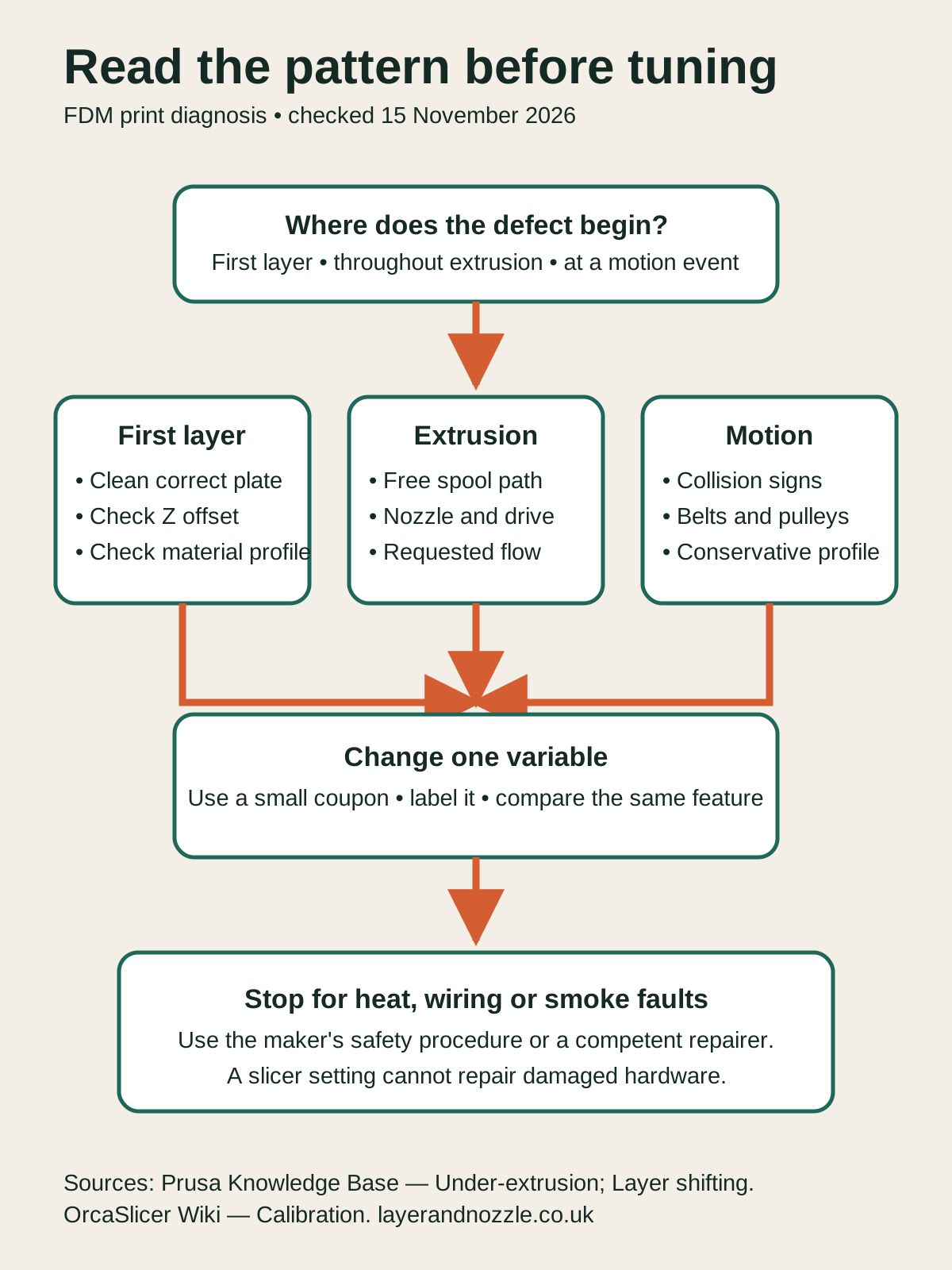
Read the shape, direction and repetition of a wall defect before changing belts, acceleration or the Z-axis.
Read the wall before touching a belt
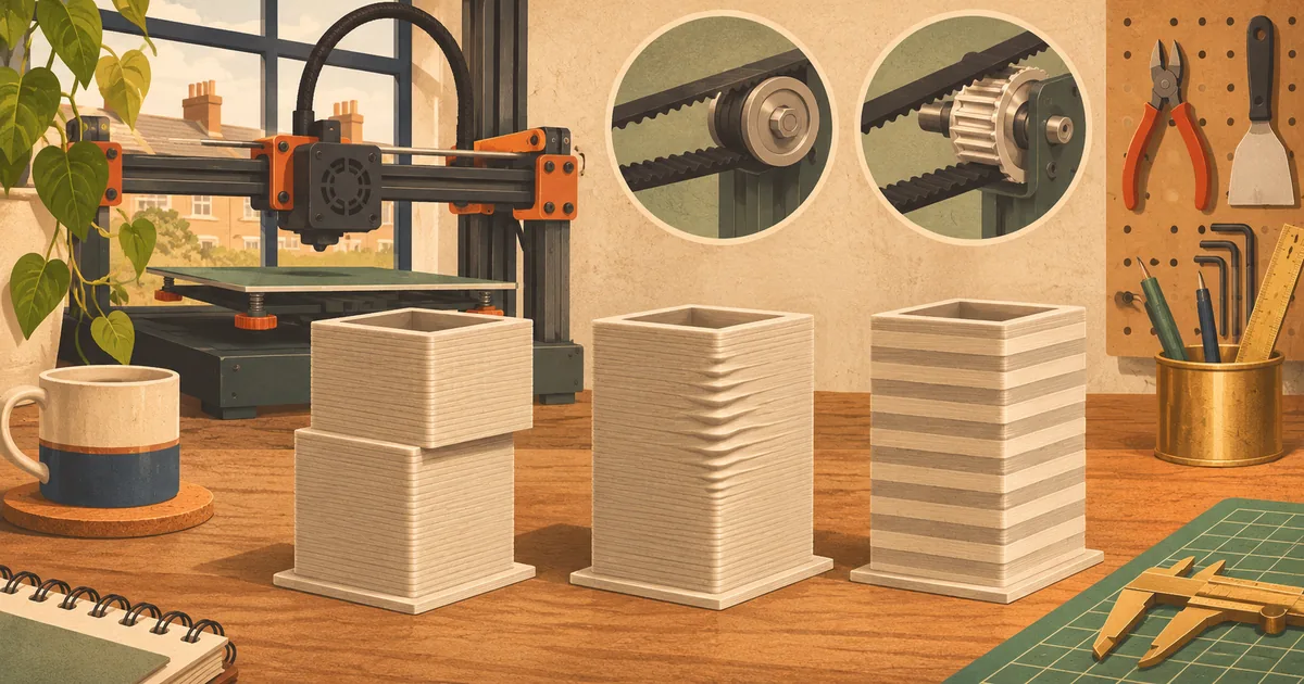
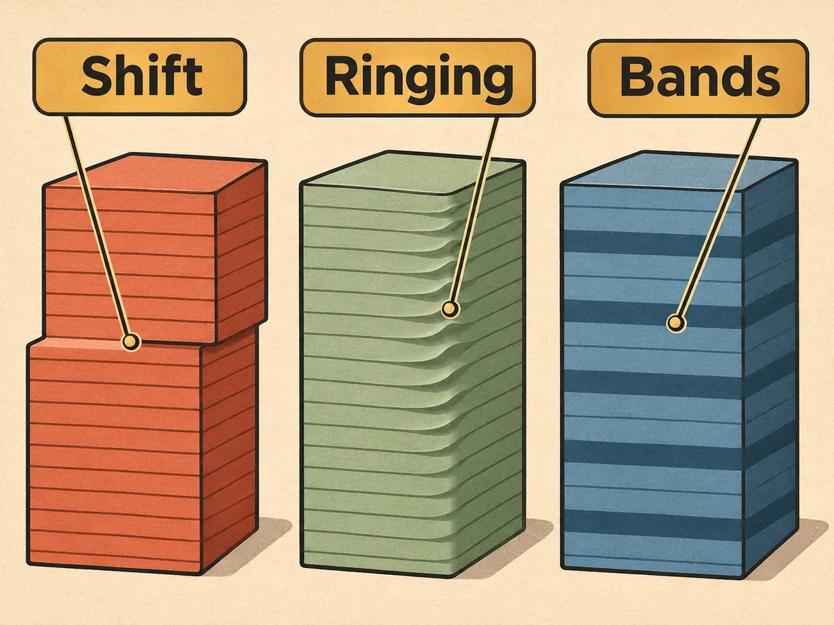
A layer shift moves the rest of the model sideways from one height. Ringing is a fading ripple after a sharp change of direction. Z-banding is a repeating change in wall position or appearance as the machine climbs. They can coexist, but they do not share one universal fix.
Mark the defect height, face and direction. Then open the sliced preview at that layer. A protruding feature at the same height may have curled into the nozzle; a sudden dense bridge may have changed motion; a repeated wave at a fixed vertical pitch points away from a one-off collision. This observation prevents “tighten everything” maintenance that can create a second fault.
Identification table
| What you see | Strong clue | First inspection | Setting worth testing later |
|---|---|---|---|
| Upper part displaced as a rigid block | Lost X or Y position at one event | Collision, belt/pulley, axis obstruction | Speed or acceleration only after mechanics |
| Ripples decay away from a corner | Frame or toolhead vibration | Loose part, printer support, belt condition | Maker input shaping or lower acceleration |
| Similar horizontal ridge repeats vertically | Periodic Z motion or periodic extrusion | Lead screw, bed/toolhead play, filament feed | None until the period is understood |
| One horizontal bulge at a model feature | Toolpath, cooling or extrusion change | Preview at the exact height | Wall order, speed, cooling or flow |
| Narrow vertical texture at certain wall speeds | Vertical fine artefact rather than Z wobble | Speed-coloured preview | Avoid resonant speed or use documented VFA test |
Layer shifts: find the lost motion
Prusa's layer-shifting guide begins with axis freedom, obstructions, belt condition, pulley security and suitable motion settings. That order matters. Firmware cannot compensate for a pulley slipping on its motor shaft or a cable snagging the bed.
With the machine cold and powered down as its manual requires, check the full travel for the affected axis. Look for a spool path, cable bundle, enclosure item or printed fragment that can catch only near one extreme. Do not force a motor-driven axis if the maker prohibits manual movement. Inspect the belt for damage and correct path; “tighter” is not automatically “correct”, so use the model's prescribed tension method.
Check pulley fasteners against the assembly manual. A pulley can grip for many moves, slip during a sharp reversal and then continue at the new position. If a fastener should bear on a motor-shaft flat, its orientation matters. Avoid raising motor current experimentally: overheating, wiring faults and driver errors belong with maker support, not slicer guesswork.
Worked layer-shift check
Suppose a tall box shifts 3 mm in X at 62 mm height. The preview shows a broad internal bridge beginning at that layer. Inspect the failed part for a raised bridge strand or nozzle scar. Check whether the X carriage travels cleanly and whether the pulley is secure. Reprint only the slice from roughly 55–70 mm as a test model, with the same orientation and bridge.
If the short test collides at the bridge, address bridge curl, cooling or travel clearance. If it shifts without contact, continue the X-axis mechanical check. If it succeeds and the full model fails at varying heights, investigate heat-related driver or motor behaviour with the printer maker. The 62 mm coincidence narrows the search; it does not prove the bridge caused the shift.
Ringing: a vibration signature
Simplify3D describes ringing as waves produced by vibration after sudden direction changes, commonly near sharp corners. The ripple spacing and decay distinguish it from a seam or periodic Z ridge.
First make the machine structurally normal. Check that the frame, toolhead covers, spool holder and build plate are secured as designed. Place the printer on a stable surface. Remove objects that rattle against it, but do not add improvised frame braces that alter geometry or obstruct ventilation.
Next compare outer-wall speed and acceleration with the official profile. High travel speed may excite the structure even when the visible wave is on an extruded wall. Reduce acceleration or speed in a copied profile, one at a time, and use a sharp-cornered tower that reproduces the echo. Keep wall order, material and cooling constant so the comparison means something.
If the printer provides automatic input-shaping calibration, use its own procedure. OrcaSlicer's calibration guide says recent printers' automatic input shaping is usually more accurate than its manual test. Do not stack an arbitrary slicer value on top of firmware compensation without understanding which layer controls the machine.
Z-banding: measure the repetition
“Z-banding” describes the appearance, not one cause. Put a ruler or calipers against the wall and record the vertical distance between similar peaks. A stable pitch is valuable evidence. Compare it with visible lead-screw rotation, coupler geometry or another repeating machine event only after consulting the printer's construction.
Inspect the Z path cold and powered down according to the manual. Look for contamination, damage, a cable that tightens at one height, incorrect lead-screw seating or play in the bed or gantry. Clean and lubricate only where, and with what, the maker specifies. Do not try to straighten a lead screw in the machine or constrain a top end that was deliberately designed to float.
Not every horizontal line is mechanical. Simplify3D's guide to lines on a print lists inconsistent extrusion, temperature variation, bed movement and Z-axis positioning among possible causes. A band aligned with a change from sparse infill to solid layers may be wall deflection or flow; inspect the preview before dismantling Z hardware.
Worked periodic-band check
A cylindrical tower shows a ridge about every 8 mm. Print a second simple tower at a different layer height but the same physical height and wall speed. If the ridge remains at the same millimetre spacing, a layer-count-specific slicer event becomes less likely. Rotate the model on the plate: a ridge that remains tied to machine X or Y suggests motion, while a texture that rotates with a seam or feature suggests toolpath.
Now compare nozzle temperature graphs if the printer exposes them, spool rotation, extruder behaviour and the Z mechanism. Do not infer a particular screw pitch from appearance alone. The useful output is a measured period, affected faces and whether it follows the machine or model—information a maker can act on.
A controlled test ladder
- Photograph the defect square-on with a scale and mark its height.
- Examine the toolpath, speed, flow and feature changes at that layer.
- Identify whether the mark is a step, a decaying echo or a periodic band.
- Inspect the matching axis using the official maintenance procedure.
- Restore the maker's current printer, filament and process presets.
- Make a small model that preserves the triggering corner, height or bridge.
- Change one relevant motion value only after the physical checks pass.
- Keep the failed and improved samples labelled with profile and firmware version.
For ringing, a yes-or-no result is “the third ripple is no longer visible at the same light angle without rounding the corner”. For a shift, it is “the upper block remains aligned and no collision mark appears”. For banding, measure whether the periodic amplitude changes; a different gloss under changed lighting is weak evidence.
Mistakes specific to these artefacts
Tensioning all belts after a Z band appears. Belts govern horizontal motion; a repeating horizontal ridge needs broader diagnosis. Incorrect tension can add wear or resonance.
Calling every wall wave ghosting. A seam repeats once per perimeter, vertical fine artefacts can be speed-related, and extrusion variation can make horizontal ridges. Use position and repetition.
Running input shaping before tightening a loose component. Compensation assumes a mechanically sound machine. A moving cover or pulley is a fault, not a resonance profile.
Changing acceleration, jerk, speed and belt tension together. The new sample cannot reveal which action mattered, and a slower print can conceal an unresolved slip.
Ignoring a detached corner. A warped edge can rise into the nozzle and cause a genuine layer shift. Preserve the collision evidence and solve adhesion rather than retuning the motion system.
When to stop printing
Stop if an axis binds, a belt is damaged, a pulley is loose, a cable is being stretched, the nozzle repeatedly strikes the model or the printer reports a driver or thermal error. Disconnect power before work involving wiring and follow the maker's service boundary. A recurring shift accompanied by hot electronics, electrical smell or unexpected resets needs manufacturer support rather than another calibration tower.
Sources
- Prusa layer-shifting diagnosis
- Simplify3D vibrations and ringing guide
- Simplify3D lines on the side of a print
- OrcaSlicer calibration order, input shaping and VFA