
Guides / Troubleshooting
Stop warping and poor bed adhesion
Separate a bad first layer from later thermal warping, then fix the plate, Z height, air, cooling and part geometry in that order.
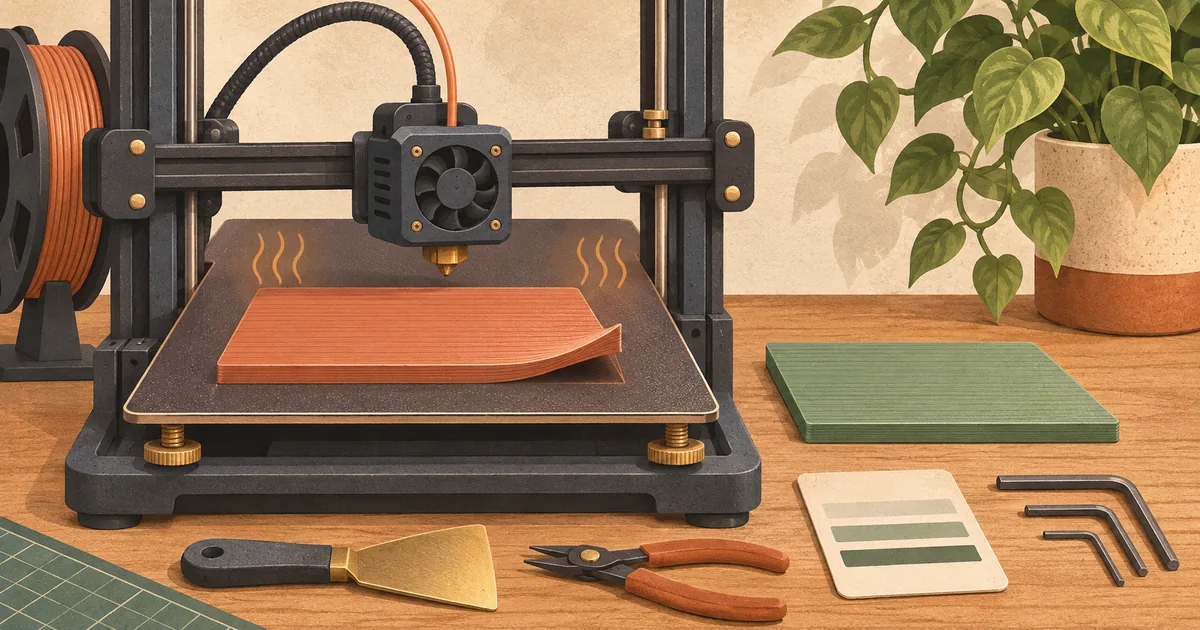
Decide when the failure begins
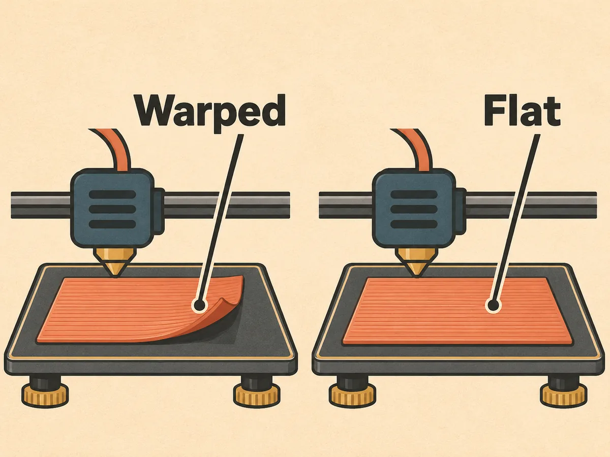
Poor adhesion and warping can end with the same curled corner, but they start differently. If the first line stays round, follows the nozzle or leaves gaps between neighbouring paths, diagnose the plate and first-layer setup. If the base begins flat and lifts after many layers, thermal contraction and part geometry have become the stronger suspects.
Watch the first layer from a safe distance and keep the failed base. Its underside records whether the nozzle was too high, too low or inconsistent across the plate. A camera time-lapse can show when a corner first moves, but do not leave the printer unattended to obtain it.
Symptom-to-check table
| Evidence | Likely area | Check next | Avoid |
|---|---|---|---|
| Separate round lines with gaps | Nozzle too far from plate or wrong flow | Z calibration, mesh and profile | Adding glue over an unformed first layer |
| Rough translucent smear, ridges pushed sideways | Nozzle too close | First-layer calibration and clean nozzle | Lowering Z further |
| Good centre, poor edge | Plate contamination, mesh or mechanical level | Clean plate, seating and maker calibration | Compensating with excessive first-layer flow |
| Corner lifts after a sound base | Thermal stress or geometry | Draughts, cooling, material, brim and orientation | Repeatedly crushing the first layer |
| Entire small part detaches suddenly | Too little contact or collision | Footprint, brim, nozzle strike and plate match | Assuming every detachment is oily PEI |
1. Match the plate to the polymer
Use the build surface and preparation method named by the printer and filament maker. Smooth, textured and coated sheets are not interchangeable, and an adhesive can act as a release layer for one polymer while improving grip for another. Prusa's material guide lists different sheet recommendations and enclosure needs across PLA, PETG, ASA, polycarbonate and flexible materials.
Clean the plate only with approved products. Handle it by the edges after cleaning. Confirm a removable sheet is seated flat with no fragment underneath; a small particle can create a local high area that no slicer compensation should be asked to hide.
If the maker calls for glue, apply a thin, even layer to a cool sheet. More adhesive is not automatically more holding force. On some very adhesive material-and-sheet combinations, the separation layer protects the coating from damage when the part is removed.
2. Read the first-layer underside
Prusa's first-layer guide shows the target as adjacent lines joined without being excessively squashed. Use the printer's current Z or first-layer calibration procedure, because probes, load cells and manual offsets differ.
Print a single-layer patch that covers the problem area rather than a tiny square in the centre. Let it cool, peel it carefully and inspect both sides. Lines that separate like string indicate insufficient contact. Deep nozzle furrows, an extremely thin transparent film or material accumulating on the nozzle indicate too much compression.
A patch that changes from one side to the other suggests plate seating, mesh calibration or mechanical geometry rather than one global offset. Repeat the maker's bed or gantry procedure; do not insert random shims under a heated bed unless the design explicitly supports them.
3. Restore the material profile
Select the exact printer, nozzle diameter, sheet and closest supported filament profile. Confirm the filament maker's nozzle and bed ranges, then begin with the supported preset. First-layer temperature, speed and cooling work together; importing one hot-bed number from an unrelated machine is not a complete profile.
Make sure the nozzle is clean before mesh probing or contact sensing. A hardened blob can change the measured reference or drag through a fresh line. Follow the hotend maker's cleaning procedure and keep tools clear of heater and thermistor wiring.
4. Control thermal change
Prusa's warping article explains that large high-temperature-material prints can lift when the difference between nozzle and ambient temperature drives shrinkage. It recommends stable ambient conditions, appropriate profiles, a grease-free surface and material-specific cooling rather than one fan rule.
Keep the printer away from an opening door, fan heater or window draught. For a material that requires an enclosure, use an enclosure approved for the machine and follow electronics-temperature and ventilation limits. Do not wrap a printer in flammable material or obstruct power supplies and cooling paths.
Cooling needs nuance. A small overhang may curl because it remains too hot, while a broad ASA wall may contract because a fan or draught cools it abruptly. Change fan behaviour only within material and printer guidance, then inspect layer bonding as well as the corner. A flat part with weakened layers is not a successful fix.
5. Reduce the corner's leverage
A long rectangular base puts contraction stress at sharp corners. A brim adds sacrificial contact around the footprint. Mouse ears add local pads at vulnerable corners. Rounded corners distribute the transition more gently, and a different orientation can shorten the longest stressed span.
Simplify3D's warping guide describes a brim or raft as a later option after temperature and environment checks. Start with a brim because it is easy to preview and usually consumes less material than a raft. Check that it actually touches the model with the intended gap; a decorative ring separated from the part cannot restrain the corner.
For your own design, avoid a huge uninterrupted slab if ribs, slots or a split assembly can meet the load. Keep wall and floor transitions gradual. For a downloaded model, rotate it, add slicer ears if available, or cut it only when the resulting joint is suitable for the application and licence.
Worked example: a PETG organiser lifts at one rear corner
The first two layers look joined, but the rear corner begins lifting at 12 mm height. Use this sequence:
- Keep the failed part and inspect its underside. If the line fusion is even, do not lower Z pre-emptively.
- Check the removable sheet is seated and clean it by the maker's PETG-compatible method. Verify that the chosen surface is recommended for PETG and that any separation layer is correct.
- Re-slice with the current printer and PETG presets. Inspect first-layer speed, bed temperature, fan ramp and the rear-corner toolpath.
- Move the printer out of the nearby door's air path or close the approved enclosure if the machine and material instructions allow it.
- Add a brim, preview its attachment around the rear corner and print a shortened section of the organiser that preserves the same footprint and wall direction.
- If that section remains flat, try the complete part. If it still lifts only as it becomes tall, investigate enclosure stability, geometry and cooling rather than adding more first-layer compression.
This example distinguishes a sound initial bond that is later overcome from a line that never adhered. The corrective evidence is the time of movement and underside, not simply the final curled shape.
Worked example: PLA lines follow the nozzle
When a small PLA part fails immediately, remove broad thermal fixes from the first pass. Confirm the correct PLA and plate profiles, clean the sheet and run the maker's first-layer calibration. Print a patch at the same plate location. If the lines remain round across the whole patch, adjust the documented Z control in its stated increments. If only one edge fails, repeat the bed-mesh or mechanical calibration instead of applying a large global offset.
Once the patch is continuous, re-slice the part with a small brim only if its footprint is genuinely narrow. A brim should solve limited contact area, not conceal a nozzle that is millimetres from the surface.
Common mistakes for adhesion and warp
Using one cleaning recipe for every sheet. Coatings and polymers differ. A solvent that is accepted on one surface can damage another; consult the plate instructions.
Touching the calibrated area after cleaning. Finger oils return the variable you just removed. Hold a flexible sheet by its edges.
Lowering Z until extrusion stops. Excessive compression can block flow, form ridges for the nozzle to hit and damage the surface.
Opening an enclosure to inspect a high-temperature print. The sudden air change can be the disturbance you are trying to diagnose. Use the printer's safe viewing method.
Increasing bed heat without a material limit. Excess heat can soften the base, exaggerate elephant's foot or exceed sheet guidance. Stay inside current maker data.
Removing the part while hot. Flexible sheets and coatings often release differently after cooling. Follow the surface instructions and avoid levering with an unapproved metal scraper.
A short decision path
If failure begins on line one, fix plate compatibility, cleanliness, seating and Z calibration. If a good base lifts later, stabilise the thermal environment and cooling, then use a brim or geometry change to reduce leverage. Retest with a section that preserves the real footprint. The aim is not maximum adhesion at any cost; it is enough predictable hold for the process without damaging the sheet or hiding a mechanical calibration fault.